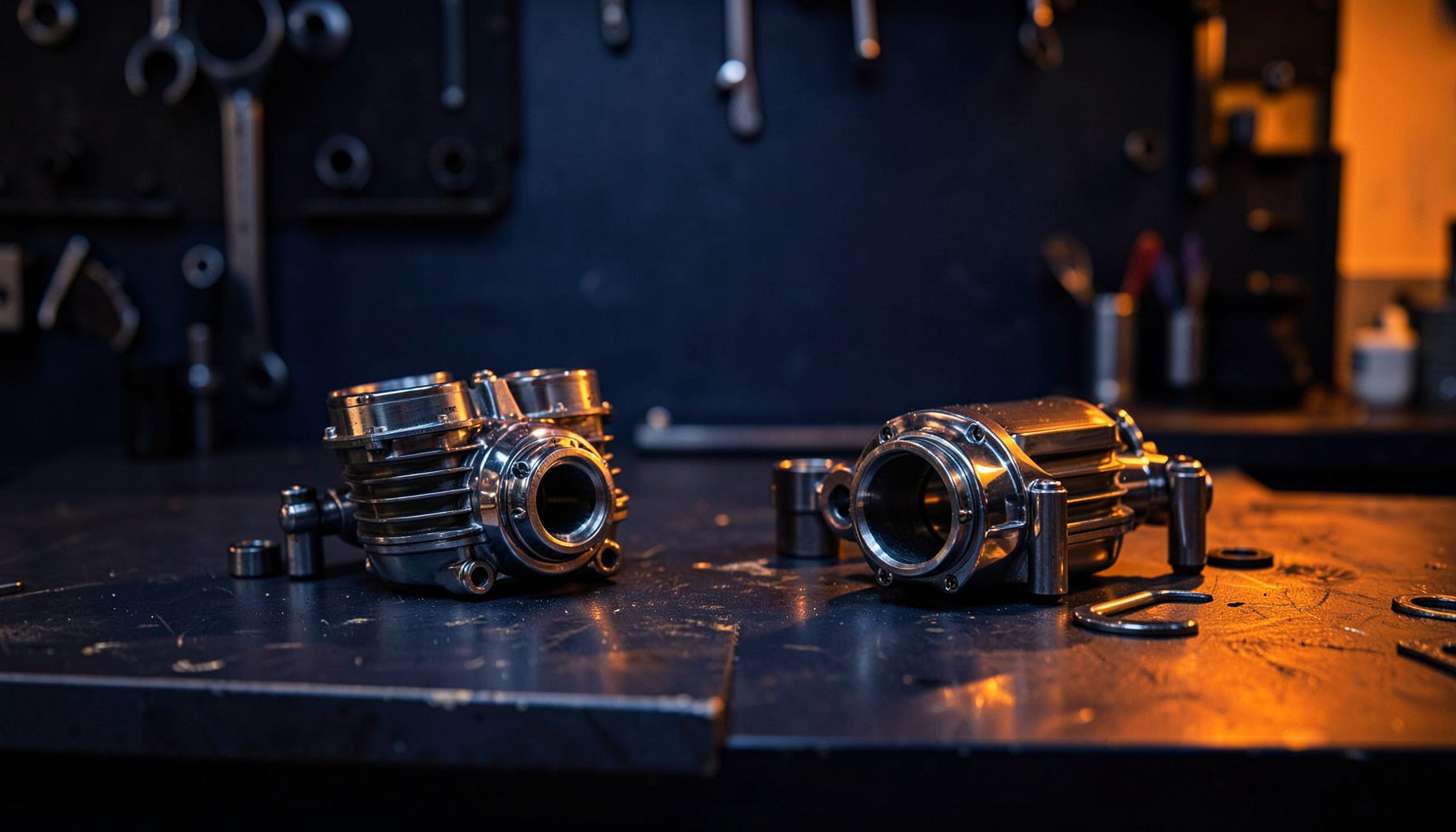
How To Test A Motorcycle Stator With A Multimeter
A motorcycle stator generates the alternating-current electricity needed to recharge the battery and power the bike’s electrical system. When it begins to fail, symptoms can include a flat battery, dimming lights, difficult starting, misfiring, or a charging warning light.
A digital multimeter can help identify a faulty stator before you replace expensive electrical components. The basic checks measure resistance between the stator windings, check for a short to ground, and test the AC voltage produced while the engine is running.
The exact readings vary between motorcycles, so keep the workshop manual nearby. A Yamaha, Honda, Kawasaki, Suzuki, Ducati, or European model may use different specifications. The guide below applies mainly to common three-phase motorcycle charging systems, but the same principles can be adapted to single-phase designs.
Prepare The Motorcycle And Multimeter
Park the motorcycle on level ground, select neutral, and allow the engine to cool before accessing the wiring. Remove the seat, side panels, or fuel tank only as required to reach the stator connector. On a hot day in Brisbane or Darwin, give the engine extra time to cool, as heat can make electrical testing uncomfortable and less safe.
Set the multimeter to DC volts for battery checks, AC volts for stator output, and resistance or continuity for winding tests. Use a meter that can display low resistance accurately. Touch the two test probes together first and note the reading; a small value caused by probe resistance may need to be deducted from the winding measurement.
Keep loose clothing and leads away from the chain, belt, sprockets, and cooling fan. Use insulated probes, avoid shorting terminals, and never allow the motorcycle to run unattended. If you need to raise the rear wheel, use a secure stand and follow the manufacturer’s workshop procedure.
Locate The Stator Connector
The stator is mounted behind the alternator or generator cover, usually on the side of the engine. Its wires travel through the engine casing to a connector leading towards the regulator-rectifier. On many three-phase systems, three matching-colour wires connect the stator to the regulator-rectifier, often yellow or white.
Identify the stator-side plug rather than relying only on wire colour. Some motorcycles have altered wiring from previous repairs, and connectors may be dirty, melted, loose, or corroded. Australian motorcycles used around coastal Newcastle, Sydney, or Perth can develop corrosion around exposed plugs, while bikes used on dusty regional roads may have contamination inside the connector.
Disconnect the plug for resistance and ground tests. Inspect the terminals for heat damage before testing. A brown, distorted connector can create charging faults even when the stator windings are healthy, so do not overlook the wiring loom, earth connections, fuses, and regulator-rectifier.
Measure Stator Winding Resistance
With the engine switched off and the stator connector unplugged, select the lowest resistance range. For a three-phase unit, label the three stator terminals A, B, and C. Measure A to B, B to C, and A to C, recording each result.
The three readings should be close to one another and fall within the manufacturer’s specified range. Some motorcycle stators have very low resistance, often below 1 ohm, while others use higher values. A reading that is open circuit, substantially higher than the other two, or noticeably inconsistent suggests a damaged winding or broken connection.
Do not judge the result by a generic number alone. A workshop manual for a Honda learner bike may specify a different resistance from a high-output Suzuki or a large touring motorcycle. Compare the measured values with the correct model-year data, particularly if the bike has an aftermarket stator or upgraded electrical accessories.
Check For A Short To Ground
Keep the stator disconnected and place one probe on each stator terminal in turn. Place the other probe on a clean engine earth or bare metal part of the engine. The meter should show no continuity, often displayed as OL, infinity, or a very high resistance.
Any clear continuity between a stator terminal and the engine casing indicates that the winding insulation may have failed. A short to ground can prevent proper charging and may damage the regulator-rectifier. Make sure the probe is touching clean metal rather than paint, oil, or oxidised aluminium before deciding that the stator is faulty.
A ground test can also reveal a fault that the phase-to-phase resistance test misses. Burnt insulation, vibration damage, and oil-soaked wiring can create intermittent problems. If readings change when the cable is gently moved, inspect the cable exit from the engine cover and the connector closely.
Test AC Output With The Engine Running
Reconnect the multimeter leads to AC volts and leave the stator connector unplugged if the manufacturer’s procedure permits it. Start the engine and measure between each pair of stator terminals: A-B, B-C, and A-C. Keep the probes firmly positioned and away from moving parts.
At idle, the AC voltage may be modest. Raise the engine speed to the test speed specified by the workshop manual, commonly around 3,000 to 5,000 rpm. Each pair should produce a similar reading, and the voltage should rise smoothly as engine speed increases. A weak or missing reading on one pair points towards a failed winding or connection.
Never allow the disconnected charging wires to contact the chassis or one another while the engine is running. Some systems can produce substantial AC voltage at higher rpm. If the service manual requires the stator to remain connected during testing, use the specified back-probing method instead of improvising.
Confirm The Charging System Before Replacing Parts
Reconnect the stator and check the battery with the engine off. A healthy, fully charged 12-volt battery commonly reads around 12.6 to 12.8 volts, although the battery’s condition and recent charging affect the result. A battery that drops sharply during starting can create symptoms that resemble a stator failure.
With the engine running, measure DC voltage across the battery terminals. Many motorcycles should show roughly 13.5 to 14.8 volts at moderate rpm, but the correct range depends on the model. A normal stator AC output with low battery voltage shifts attention towards the regulator-rectifier, wiring, fuses, or earth connections.
If the charging voltage is excessive, stop testing and investigate promptly because overcharging can damage the battery, bulbs, instrument electronics, and accessories. Australian riders who fit heated grips, auxiliary lighting, phone chargers, or touring equipment should also check that the electrical load does not exceed the system’s capacity. Pattern Parts provides replacement charging components, electrical parts, and maintenance items for many motorcycle makes and models, helping you match the repair to the bike rather than guessing from symptoms.
Use the recorded resistance, ground, AC output, battery voltage, and connector condition to make the diagnosis. When the readings are outside specification, replace the stator with a suitable OEM-equivalent or quality aftermarket part and inspect the regulator-rectifier at the same time. Browse Pattern Parts for motorcycle electrical components, charging-system spares, and model-specific maintenance parts to keep your bike reliable on urban commutes, long highway trips, and remote Australian routes.